top of page

Analog to Digiltal Filter Transformation

A digital filter (low pass, high pass, band pass and band stop) of the transfer function H(z) can be obtained from the transfer function H(s) of an designed analog filter as the block diagram shows below. The procedure of this method is first by transforming an analog filter (low pass, high pass, band pass, band stop, narrow band) into analog low pass prototype using Inverting Pascal matrix equations and then transforming into a desired digital filter using Analog to digital filter Pascal matrix eqaution.


Transforming any analog filter to a digital filter using Analog to digital Pascal matrix eqaution

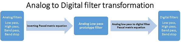
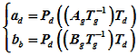
From the block diagram, an matrix equation can be derived called "Analog to Digital filter Pascal matrix equation" as written below

Frequency transformation from s-domain into z-domain

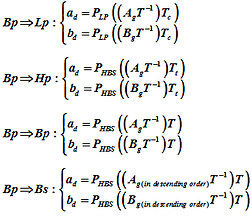
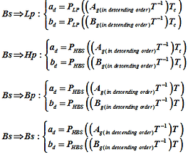
Analog Low pass to Digital filters

Transforming an analog low pass to digital filters using Analog to Digital filter Pascal matrix equation

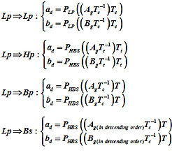
Analog High pass to Digital filters

Transforming an analog high pass to digital filters using Analog to Digital filter Pascal matrix equation

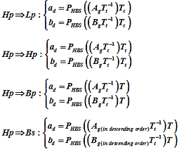
Analog Band pass to Digital filters

Analog Band stop to Digital filters

Transforming an analog band pass to digital filters using Analog to Digital filter Pascal matrix equation
Transforming an analog Band stop to Digital filters using Analog to Digital filter Pascal matrix equation

Copyright © 2015 -  Analog to Analog Filter Pascal Matrix Equation - Analog to Digital FilterPascal  Matrix Equation - Digital to Digital Filter Pascal Matrix Equation - All Rights Reserved - Author by Nguyen Si Phuoc.

  • Facebook Basic Square
  • Pinterest Social Icon
  • YouTube Classic
  • Twitter Basic Square
  • Google+ Basic Square
  • filtertofilterPascal1.jpg 2015-3-24-9:33:6
Filter design using Pascal matrix equation
bottom of page